.jpg)
A basic idea in electrical engineering, impedance—Z—represents the overall resistance a circuit offers to alternating current (AC). It generates a complicated number expressed in ohms (Ω) by combining resistance (R) with reactance (X), therefore including the effects of capacitors and inductors. Design and analysis of AC circuits, guarantee of best performance in power distribution, signal transmission, and communication systems, depend on an awareness of impedance.
Calculating impedance lets engineers forecast resonance effects, power losses, and voltage drops, therefore enabling more dependable and effective circuit designs. Applications involving audio equipment, RF PCB systems, and power electronics, where impedance matching is essential to reduce reflections and losses, depend especially on this knowledge. Mastery of impedance calculations guarantees correct component interaction inside a circuit, therefore improving both longevity and performance.
Key Highlights
- Impedance is a measurement of opposition a circuit presents to the passage of alternating current.
- There are three types of impedance: resistive, capacitive, and inductive impedance.
- Reactance refers to the resistance to the flow of alternating current (AC) resulting from inductors and capacitors.
- Impedance Triangle is a graphical depiction of the interactions among the components of impedance: resistance (R), reactance (X), and impedance (Z).
- You must understand the components, use the correct formula, frequency, and consider phase shift while calculating the impedance.
What Is Impedance and Its Significance?
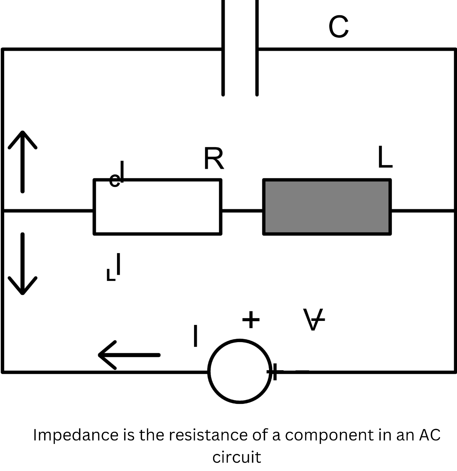
Represented by the symbol "Z," impedance is a measurement of opposition a circuit presents to the passage of alternating current (AC). Unlike resistance, which only pertains to direct current (DC) circuits, impedance comprises both resistance (R) and reactance (X), therefore defining a complicated number expressed in ohms (Ω). Its sign, "Z," comes from its beginnings in mathematical depictions of AC circuits, where the computation of real and imaginary components combines.
In AC circuits, by influencing the voltage and current relationships, impedance becomes rather important. It affects power dissipation, resonance, and signal integrity as well as the amount of current that will pass a circuit for a given voltage.
Through their reactance, which changes with the frequency of the AC signal, components such as capacitors and inductors add to impedance. Effective circuit design thus depends on an awareness of impedance, which guarantees optimal interaction between electronic components and system performance. Applications like radio frequency (RF) circuits, transmission lines, and audio systems depend especially on impedance matching to reduce signal loss and power inefficiency.
Impedance Symbol and Key Formula
In electrical engineering, impedance—shown by the symbol "Z”—is a complicated number that defines the resistance a circuit offers to alternating current (AC). The convention for computing impedance is:
Z = R + jX
Where:
- Z is impedance (in ohms),
- R is resistance (in ohms),
- jX is the reactance (in ohms),
- j is the imaginary unit ( √-1). It indicates the phase difference between voltage and current, due to inductive or capacitive components,
- X can be positive for inductive reactance (XL) or negative for capacitive reactance (XC).
To calculate impedance, follow these steps:
- Determine Resistance (R): Measure or identify the resistance of the circuit, usually caused by resistors or conductive elements.
- Calculate Inductive Reactance (XL): If the circuit contains inductors, calculate the inductive reactance using the formula: XL = 2πfL Where f is the frequency in hertz and L is the inductance in henries.
- Calculate Capacitive Reactance (XC): If capacitors are present, calculate the capacitive reactance using the formula: XC = 1 / (2πfC) Where C is the capacitance in farads.
- Combine the Components: Plug the values of R and X (where X = XL - XC) into the impedance formula: Z = R + jX. The output will provide you both impedance's magnitude and phase angle.
Different Types of Impedance
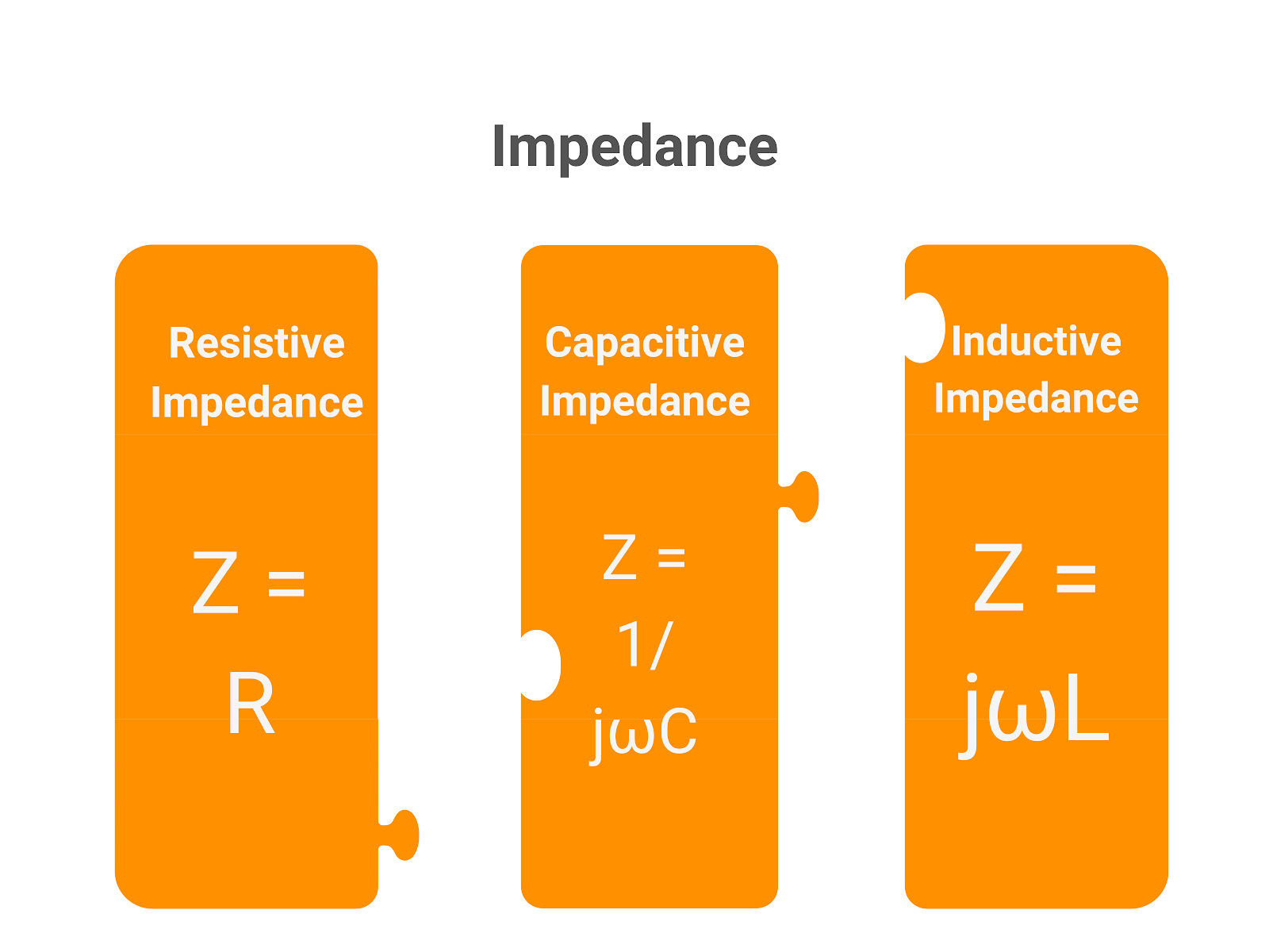
In electrical circuits, resistive, capacitive, and inductive impedance are three basic forms of impedance. Every kind shows a different method. Check out them.
- Resistive Impedance: This kind of impedance is entirely real and found in PCB components like resistors, where impedance equals resistance. Resistive circuits cause no phase shift between the voltage and current since they remain in phase with one another. Resistive impedance is found to be just Z = R, where R is the ohm resistance. Without frequency-dependent behavior, this is the simplest basic kind of impedance and easy to compute.
- Capacitive Impedance: In circuits with capacitors, capacitive impedance resists voltage fluctuations and results from Capacitors store and release energy in the electric field to produce a phase shift whereby the current leads the voltage by 90 degrees. As the frequency of the AC signal rises, the capacitive reactance (XC) falls; the impedance is obtained from the formula Z = 1 / (jωC), where ω is the angular frequency and C is the capacitance in farads. Higher frequencies pass more readily when capacitive impedance is inversely proportional to the signal frequency.
- Inductive Impedance: In circuits including inductors, inductive impedance results from the impedance opposing variations in current. Because inductors store energy in a magnetic field, the current lags the voltage by ninety degrees. As frequency increases, the inductive reactance (XL) rises; the impedance is computed as Z = jωL, where L is the henries inductance. Higher frequencies come across more resistance since inductive impedance rises with frequency.
Different forms of impedance impact circuit behavior in different ways, therefore affecting variables including resonance, phase shift, and signal attenuation. Combining different kinds in complex circuits produces a total impedance that has to be precisely computed to guarantee best performance.
Impedance in RLC Circuits: A Detailed Overview
In RLC circuits—those including resistors (R), inductors (L), and capacitors (C)—impedance (Z)—the total opposition the circuit presents to the flow of alternating current (AC). Resistance, inductive reactance, and capacitive reactance taken together account for this opposition.
- Resistive Impedance (R): The resistor in an RLC circuit offers only actual impedance and constantly opposes both AC and direct current (DC). The resistive impedance of the resistor is just Z = R since voltage and current have no phase difference.
- Inductive Impedance (XL): When current passes through inductors, they store energy in a magnetic field, lagging the voltage by 90 degrees. Calculated as XL = jωL, where ω is the angular frequency and L is the inductance in henries, the impedance owing to the inductor, sometimes known as inductive reactance, rises with frequency.
- Capacitive Impedance (XC): Capacitors store energy in an electric field, hence the current leads the voltage by ninety degrees. Calculated as XC = 1/jωC, the capacitive reactance falls with frequency; C represents the capacitance in farads.
The total impedance of an RLC circuit is the vector sum of capacitive reactance, inductive reactance, and resistance. The inductive and capacitive reactances detract from one another since their orientations are opposite. One finds the overall impedance by:
Z = R + j(XL - XC)
This formula aggregates the imaginary part—net reactance—with the real part—resistance. The circuit behaves inductively if XL > XC; it behaves capacitively if XC > XL. The amplitude and phase of the AC signal depend on the total impedance; so, resonance—where XL = XC—minizes impedance and maximizes current. Designing effective AC systems depends on an awareness of impedance in RLC circuits, especially in uses like filters, oscillators, and tuning circuits.
Calculating Impedance in RLC Circuits
Combining the effects of resistance (R), inductive reactance (XL), and capacitive reactance (XC), impedance (Z) in RLC circuits shows the whole opposition to current flow. The formula for determining the overall impedance in a series RLC circuit is:
Z=√{R²+(XL−XC)²}
Breaking Down the Formula:
- Z (Impedance): The circuit's general impedance expressed in ohms (Ω). It is the resistive, inductive, and capacitive element vector sum.
- R (Resistance): R, or resistance, is the actual, frequency-independent opposition to current resulting from circuit resistors. It's expressed in ohms (Ω).
- XL (Inductive Reactance): Calculated as XL = 2πfL, where f is the frequency in hertz and L is the inductance in henries, XL (Inductive Reactance) is the resistance to current flow owing to inductors. Frequency raises the inductive reactance.
- XC (Capacitive Reactance): Calculated as XC = 1 / (2πfC), XC (Capacitive Reactance) is the resistance to current flow caused by capacitors in farads. Frequency lowers the capacitive reactance.
Depending on whether XL or XC predominates, (XL - XC) in the calculation denotes the net reactance—which can be either inductive or capacitive. Crucially important for AC circuit behavior, the total impedance Z influences the magnitude and phase of the current passing in the circuit.
Understanding Reactance: Inductive and Capacitive
In AC circuits, reactance—the resistance to the flow of alternating current (AC) resulting from inductors and capacitors—is a fundamental component of impedance. Reactance just affects AC and its magnitude depends on the frequency of the current; unlike resistance, which applies equally to both AC and direct current (DC). Along with resistance, reactance significantly determines the total impedance of a circuit and helps to phase the voltage against the current.
Inductive Reactance (XL):
Inductive reactance happens in circuits using inductors—coils. Inductors create a magnetic field that resists changes in current by lagging the current behind the voltage by 90 degrees. Inductive reactance has the formula:
XL = 2πfL
Where:
- XL is the inductive reactance, measured in ohms (Ω),
- f is the frequency of the AC signal in hertz (Hz),
- L is the inductance of the coil in henries (H).
Inductive reactance rises with increasing frequency, hence inductors provide more resistance to current flow at higher frequencies. In high-frequency uses like radio and telecommunications systems, this is very crucial.
Capacitive Reactance (XC):
In circuits including capacitors, capacitive reactance results. Capacitors resist voltage and store energy in an electric field, therefore leading the current to follow the voltage by 90 degrees. Capacitive reactance has a formula:
XC=1/(2πfC)
Where:
- XC is the capacitive reactance, measured in ohms (Ω),
- f is the frequency of the AC signal in hertz (Hz),
- C is the capacitance in farads (F).
Capacitive reactance falls with increasing frequency, so at higher frequencies capacitors provide less resistance to current flow. In filtering applications, where they can let high-frequency signals flow while blocking lower frequencies, this feature makes capacitors valuable.
Role in Impedance Calculation:
The combined action of inductive and capacitive reactances determines the total impedance of an AC circuit. In a circuit, these reactances oppose one another; so, the net reactance is XL - XC, the difference between them. Designing circuits that run effectively over many frequencies—including tuning circuits, filters, and oscillators— depends on an awareness of reactance.
The Impedance Triangle and Its Practical Use
In AC circuit analysis, the Impedance Triangle is a graphical depiction of the interactions among the components of impedance: resistance (R), reactance (X), and impedance (Z). This is a right-angled triangle in which every side relates to a fundamental component of impedance.
- Resistance (R): Representing the simply resistive opposition to current flow, this creates the horizontal (adjacent) side of the triangle.
- Reactance (X): Reactance (X) is the vertical, opposing side of the triangle and combines capacitive and inductive reactance in the circuit. Here one uses the net reactance (XL - XC).
- Impedance (Z): The hypotenuse of the triangle, impedance (Z) shows the whole resistance to current passage in the circuit. Resistance and reactance taken together form the vector total.
The impedance triangle is constructed based on the Pythagorean theorem, which relates the sides of a right triangle:
Z=√(R²+X²)
Where:
- Z is the impedance (hypotenuse),
- R is the resistance (adjacent side),
- X is the reactance (opposite side).
Significance of the Impedance Triangle
Engineers and technicians can see how reactance and resistance add to a circuit's overall impedance by means of the impedance triangle. Furthermore simpler calculations of the impedance and phase angle (φ), which denotes the phase difference between voltage and current, Trigonometry allows one to find the phase angle by:
φ=arctan(X/R)
This angle is important because it shows the extent of the phase shift caused by the inductive or capacitive reactance in the circuit.
Practical Use of the Impedance Triangle
In AC circuit design and analysis, the impedance triangle is particularly helpful since it streamlines the computation of the total impedance in cases of both resistance and reactance presence. Knowing two sides of the triangle—e.g., resistance and reactance—one can readily determine the overall impedance. Furthermore, the phase angle may be found; this is essential for uses including impedance matching in RF circuits and power factor adjustment. Practically, especially in resonance and filtering uses, the impedance triangle helps to visualize how reactive components affect the circuit, therefore permitting more precise predictions of circuit behavior and more efficient designs.
Impedance Formulas and How to Apply Them
Analyzing AC circuits—especially those incorporating resistors, capacitors, and inductors—requires the indispensable tools known as impedance formulations. Expressing in ohms (Ω), impedance (Z) is a complicated quantity combining resistance (R) and reactance (X). Different formulas enable one to determine impedance in many combinations, including complex impedance.
Basic Impedance Formulas:
- Resistive Impedance (R):some text
- Formula: Z = R
- In just resistive circuits, there is no reactance involved; impedance equal the resistance. This is usual in either DC or AC circuits devoid of inductors or capacitors.
- Inductive Reactance (XL):some text
- Formula: XL = 2πfL
- Inductive reactance increases with frequency and depends on the inductance (L) of the circuit.
- Capacitive Reactance (XC):some text
- Formula: XC = 1 / (2πfC)
- Capacitive reactance decreases with frequency and depends on the capacitance (C) of the circuit.
- Series RLC Circuit Impedance:some text
- Formula: Z = √(R² + (XL - XC)²)
- The impedance of a series circuit comprising capacitors, inductors, and resistors is the net reactance less resistance.
- Parallel RLC Circuit Impedance:some text
- Formula: 1/Z = √(1/R² + (1/XL - 1/XC)²)
- In parallel circuits, impedance calculations involve combining reciprocal values of resistances and reactances.
Complex Impedance:
In circuits with AC, impedance is often represented as a complex number to account for both magnitude and phase differences:
Z=R+jX
Where:
- R is the resistance (real part),
- X is the reactance (imaginary part),
- j is the imaginary unit (√-1).
In this sense, impedance catches the phase shift between current and voltage as well as the resistance to current (magnitude). In power calculations and AC circuit analysis, it is rather often utilized.
Applying Impedance Formulas in Real-World Scenarios:
- Power Distribution: By guaranteeing that maximum power is transmitted from a source to a load, impedance matching helps to lower reflections in power distribution systems and RF applications.
- Circuit Design: Engineers design filters, oscillators, and amplifiers by choosing components (resistors, capacitors, inductors) that offer the intended impedance characteristics using impedance calculations.
- Resonance Tuning: In RF systems or radios, impedance formulas balance inductive and capacitive reactances to produce resonance, hence optimizing signal power and helping to tune circuits to certain frequencies.
Reactance vs. Impedance: Key Differences
Both important ideas in AC circuit analysis, reactance and impedance have different functions. Reactance (X) is the resistance to the alternating current (AC) produced by inductors and capacitors especially. The frequency-dependent quantity influences the behavior of these parts in an AC circuit. Two kinds of reactance exist:
- Inductive Reactance (XL): Increases with frequency, opposing changes in current.
- Capacitive Reactance (XC): Decreases with frequency, opposing changes in voltage.
The formulas are:
- XL = 2πfL
- XC = 1 / (2πfC)
Impedance (Z), on the other hand, is a more comprehensive measure of opposition in AC circuits. It includes both resistance (R) and reactance (X), and is a complex quantity expressed as:
- Z = R + jX
Where R is the resistance, and jX represents the reactance (with j indicating the phase difference).
Reactance is applied in circuit design to examine and project the behavior of capacitors and inductors at various frequencies. The overall opposition to current flow is computed and the phase shift between voltage and current by means of impedance, which combines reactance with resistance. Designing effective AC circuits—including filters, amplifiers, and resonant systems—requires an awareness of both.
How Capacitance Converts to Impedance
In AC circuits, capacitance turns to impedance since capacitors oppose voltage fluctuations. Inversely connected to both the capacitance (C) and the frequency of the AC signal (f), the impedance of a capacitor—also known as capacitive reactance (XC—is The capacitive reactance is computed with this formula:
XC= 1/2πfC
Where:
- XC is the capacitive reactance in ohms (Ω),
- f is the frequency in hertz (Hz),
- C is the capacitance in farads (F).
The impedance falls with increasing frequency, so the capacitor lets more current pass. On lower frequencies, on the other hand, the capacitive impedance is higher, so providing more resistance to current flow.
Example:
Suppose a circuit has a capacitance of 10 microfarads (10 µF) and operates at a frequency of 1000 hertz (1 kHz). The capacitive reactance is calculated as:
XC=1/2π(1000)(10×10−⁶)≈15.9 Ω
This indicates that the capacitance causes an almost 15.9 ohm impedance at 1 kHz. Determining how capacitors affect current flow at different frequencies—that is, in filters, oscillators, and power supply circuits—key in AC circuit design.
Key Takeaways from Impedance Calculations
- Understand Impedance Components: The mix of resistance (R) and reactance (X) is impedance (Z). Reactance incorporates both inductive (XL) and capacitive (XC) components; it is expressed as a complex quantity, Z = R + jX. In AC circuits, always regard the vector sum of resistance and reactance.
- Use the Correct Formulas: The overall impedance of series circuits is determined by Z = √(R² + (XL - XC)²). The reciprocal formula 1/Z = √(1/R2 + (1/XL - 1/XC)²) applies to parallel circuits. Make sure you apply the right formula considering the circuit layout.
- Frequency Matters: Reactance changes according to frequency. Whereas capacitive reactance (XC = 1 / 2πfC) declines with frequency, inductive reactance (XL = 2πfL) increases. Calculation of accurate impedance calls for knowledge of the operational frequency.
- Consider Phase Shift: Phase shifts between current and voltage are introduced by impedance. Make sure you consider these changes especially in relation to design for resonance, signal integrity, and power economy.
Common Mistakes to Avoid:
- Neglecting Reactance: Ignoring reactance and concentrating just on resistance results in inaccurate impedance values especially at higher frequencies.
- Wrong Circuit Configuration: Inaccurate computation occurs from applying series formulas to parallel circuits or vice versa.
- Ignoring Frequency Effects: Especially in AC circuits, miscalculations may arise from not changing reactance values depending on frequency.
Practical Tips:
- Use Impedance Matching: To maximize power transfer and minimize reflections, ensure source and load impedances are matched.
- Leverage Tools: Utilize calculators and simulation tools to verify complex impedance calculations, particularly in high-frequency circuits.
Conclusion
Fundamental in nature, impedance computation is especially important in AC circuit design and analysis in electrical engineering. From audio systems to RF communications, engineers can maximize power transmission, reduce signal loss, and guarantee circuit stability across many uses by knowing impedance. In circuit design, effectively using impedance calls for consideration of frequency, component values, and the circuit layout (series vs. parallel). Reliable circuit performance and precise analysis depend on avoiding typical errors include neglect of reactance and formula application issues. Complex designs can be assisted by tools like impedance simulators, therefore enabling improved outcomes.