Every PCB is made up of a network of electrical components. Some of the prominent elements are resistors, inductors, capacitors, and so on. Even though understanding all of them is challenging, basic knowledge of PCB components is a must-have in the manufacturing process. This blog will share a comprehensive understanding of PCB components, including what they are made up of and how to solder them.
Key Highlights
- In simple words, a PCB component is a part of the board that is essential for its functioning.
- PCB is made up of many components like resistors, conductors, inductors, transistors, etc., and each element plays a role in its functioning.
- Manufacturers must select the right equipment, solder techniques, and group the solder components in the right order.
- Some of the main reasons for PCB short circuits are exposure to contaminants, age of components, manufacturing defects, misalignment of solder paste, and internal growth of CAF.
What is a PCB Component?
In simple words, a PCB component is a part of the board that is essential for its functioning. There are two main types of PCB components: active and passive. Active components are the parts which need an external force to work. For example, transistors are active components that can amplify weak electrical signals into stronger ones.
Passive components work without any external power sources and cannot influence the current flow. The capacitor is a type of passive component that stores electrical energy and releases it when needed. However, the key difference lies in the fact that active components can control the flow of current while passive cannot.
What PCB Components Are Printed Circuit Boards Made Of?
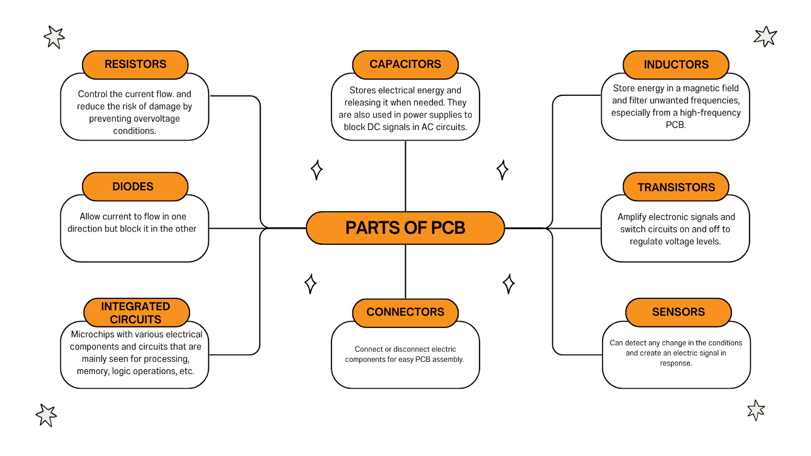
Each PCB component plays a crucial role in the functioning of a board. Check out some of the most common PCB components and their functions:
- Resistors: Resistors are one of the basic components of PCB that help in controlling the current flow and reducing the risk of damage by preventing overvoltage conditions.
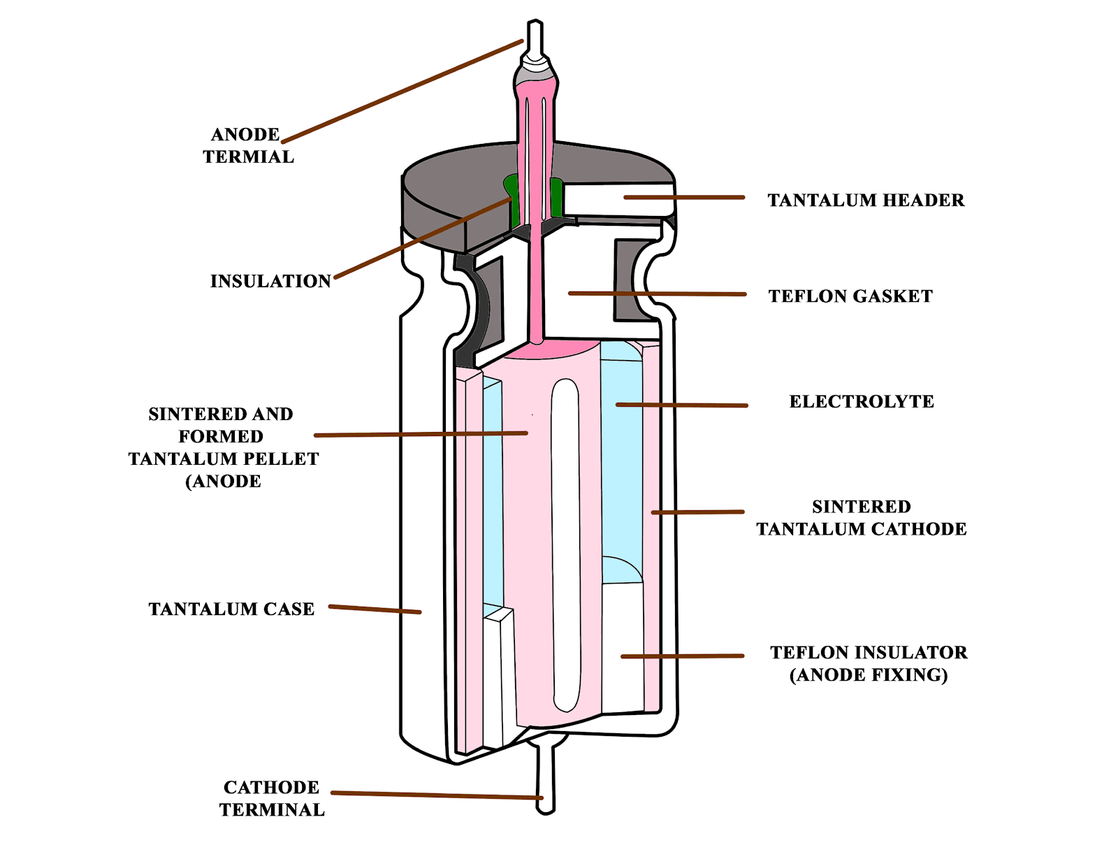
- Capacitors: These are components that are responsible for storing electrical energy and releasing it when needed. Manufacturers also use them in power supplies to block DC signals in AC circuits.
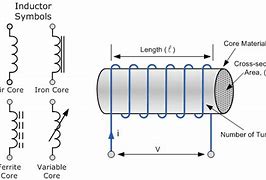
- Inductors: just like capacitors, inductors also store energy. But there is a key difference- inductors store energy in a magnetic field. It is also used to filter unwanted frequencies, especially from a high-frequency PCB.
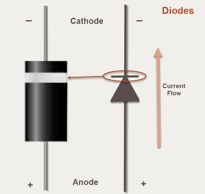
- Diodes: Components that allow current to flow in one direction but block it in the other are called diodes.
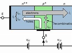
- Transistors: As mentioned earlier, transistors are semiconductor devices that can amplify electronic signals.
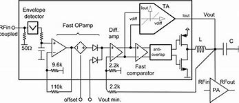
- Integrated Circuits: Integrated Circuits (IC) are microchips with various electrical components and circuits that are mainly seen for processing, memory, logic operations, etc.
- Connectors: as the name suggests, connectors are used to connect or disconnect electric components for easy PCB assembly.
- Sensors: Sensors are those components that detect any change in the conditions. As soon as they detect an abnormality, they create an electric signal in response.
How to Solder PCB Components?
PCB soldering is a crucial process in manufacturing that is to be done carefully in the presence of well-trained professionals. Here are the steps to follow:
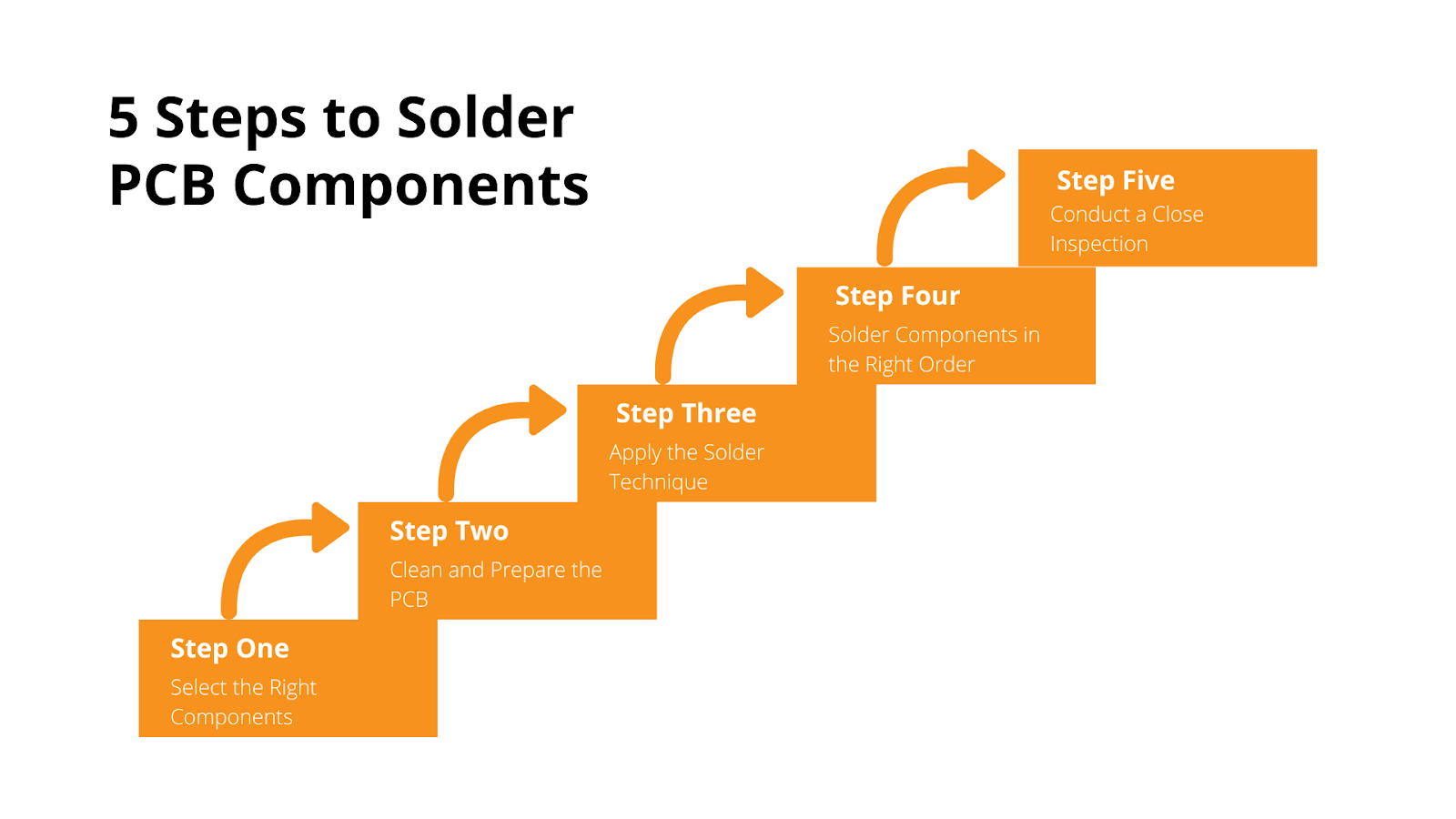
1. Select the Right Components
First of all, acquire the right materials for the process from trusted sources. Check out some must-have components and how to select them:
- Soldering iron: Go for a temperature-control iron with a fine precision point.
- Solder: As per stats, 70% of PCBs are used in modern electronic devices like computers. Therefore, it is always better to choose lead-free rosin-core solder as it is a safer option. Go for the thinnest one, preferably around 0.5-1.0 mm in diameter.
- Cleaning Supplies: Always keep cleaning materials such as isopropyl alcohol and cotton swabs within reach to clean the iron tip.
2. Prepare the PCB
Use the cleaning supplies to clean the PCB surface of any contaminants. Then, place it on a heat-resistant pad at a comfortable angle for manufacturers. For better alignment, bend the components slightly at a 45-degree angle and fix them firmly on the PCB pad.
3. Solder Technique Application
The next step is to heat the PCB pad along with the soldering iron tip. While heating, coat the joints with the solder mix. Use the soldering iron to regulate the heating process. Keep the temperature low as compared to welding. After the process, the board must be cooled off before moving.
4. Solder Components in the Right Order
First of all, group the PCB components by function for soldering. Here are some things to check out while soldering components:
- Place them through holes at a safe distance from areas where heat can dissipate.
- Connectors must be at the end of the board for easier connection.
- Copper traces must be allocated in such a way that they are not too close or far away.
- While placing, ensure that the legs of the components are bent on the solder side to avoid falling.
5. Close Inspection
Last but not least, properly inspect all solder joints with magnifying glasses. Check out whether there are any bridges or cold joints. If there is any flux residue on the PCB surface, clean it up using the supplies.
What Causes Short Circuits On A PCB?
Short circuits are one of the most dangerous defects that can ruin the entire functioning of a PCB. It is important to know the reason for the problem and solve it on time to prevent any further damage. Check out some common reasons for PCB short circuits:
1. Exposure to contaminants
External exposure to PCB is obviously a common reason for short circuits in a PCB. Some of the common causes of such external exposure are:
- Poor cleaning may result in flux residues which may become more conductive over time.
- Exposure to moisture and humidity can cause corrosion.
- Without proper coverings, Dust and debris can accumulate on the PCB which can cause short circuits.
- Growth of copper dendrite between conductors.
2. Internal growth
Sometimes contaminants may grow inside the inner layers of PCB as a result of some chemical reactions rather than infiltrating from outside. For example, an electrochemical reaction called Conductive Anodic Filamentation (CAF) may create filaments if metallic or conductive salts are present in the multilayer PCBs.
3. Manufacturing Defect
Incorrect placement of PCB components may cause serious short-circuit problems. That's why it is important to do the PCB fabrication process perfectly, aligning each component in such a manner that none are too close or far away from each other.
4. Misalignment of Solder Paste
Solder paste is to be evenly applied to PCB pads and holes, during the manufacturing. In case there is a mismatch, the gap between two PCB pads may be bridged and an unintentional connection may be caused.
5. Age of Components
Over time, PCB components may degrade. As a result, they may be more subjected to short circuits in high temperatures and humidity.
Final Thoughts
Ignorance of PCB components and basics is the root cause of many manufacturing defects. Manufacturers must have a comprehensive knowledge base to take up a unique approach for each PCB production process, after analysing various aspects like the tools, components, etc. Remember, the key to successful PCB manufacturing lies in an in-depth knowledge of its components and how they work.
%20(1).png)

