One of the most safest methods to join electrical parts together in a Printed Circuit Board (PCB) is a through hole. When it comes to PCB manufacturing, these holes are needed to make sure that the electrical connections are strong and that the mechanical connections are strong.
As a seasoned expert in the industry, we, at Lion Circuits, exactly know what it takes to create the best PCB solutions. We know how important it is to master through holes, to make electronic systems last longer and work better. Proper knowledge of the usage of through hole techniques is a must as it ensures the creation of circuit designs that are strong and reliable.
Keep reading to know What exactly is a through hole to have a better understanding of this structural element.
Key Highlights
- Through-hole is a pre-drilled hole that allows electronic components to be inserted and soldered to the board.
- Resistors, capacitors, and diodes are all examples of PCB components that are widely made using through-hole technology.
- The choice of whether Through Hole or Surface Mount is to be used depends on various factors like environmental stress, mechanical strength, etc.
- You must consider several things like mechanical stability, hole size, temperature control, and layer management during PCB layout for Through-Hole.
- While designing a through hole, you must select the hole size carefully, arrange the grids uniformly, and ensure thermal vias placement.
What is a Through Hole?
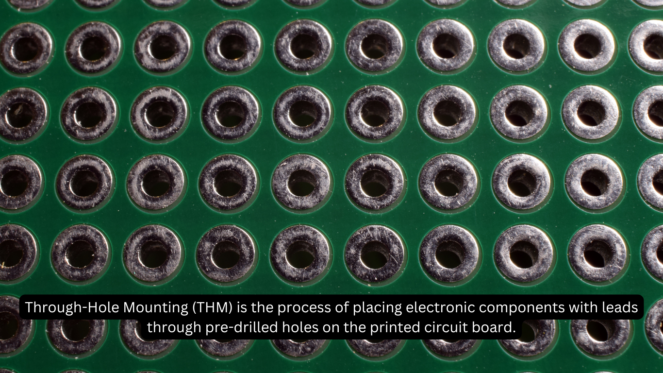
In the context of printed circuit boards, a through hole is a pre-drilled hole. It allows electronic components to be inserted and soldered to the board. These holes run the entire thickness of the PCB, thereby allowing connections from one side to the other.
The basic construction of a through hole consists of the drilled hole itself. It is usually lined with a conductive substance like copper, and PCB pad on both sides of the PCB where components are soldered. This design ensures that the components are securely fastened to the board. Thus, the board gets its stability and durability.
Importance
- Mechanical connections: Through-holes form strong mechanical connections. It ensures that components are securely fastened. In fact, the connections are secured even under physical stress or vibration.
- Electrical Connections: They enable reliable electrical paths across different PCB layers, which is critical for complex circuit designs. Through holes are critical for obtaining both mechanical strength and electrical integrity in PCB manufacturing.
A Brief History of Through Holes
Through holes have been used in PCB manufacture since the 1940s. It is when the earliest PCBs were designed for military and industrial uses. Initially, components were manually soldered on single-sided PCBs. The emergence of double-sided and multilayer PCBs in the 1950s needed more dependable connecting methods. This requirement resulted in the widespread use of through-hole technology today. Nevertheless, automated assembly techniques and mass production were introduced in the 1960s and 1970s. It results in substantial advances in PCB manufacturing.
Key milestones in the development of through-hole techniques include the 1950s development of plated through holes; it had improved connection reliability. Along with that, the 1970s emergence of automated insertion machines increased production efficiency. In the 1980s, there was the rise of surface-mount technology (SMT). It began to complement through-hole methods and allowed for more compact and complex designs. Despite the emergence of SMT in modern electronics, through-hole technology is still required for certain applications that require strong mechanical connections.
Components that Use Through Holes
Resistors, capacitors, and diodes are all examples of PCB components that are widely made using through-hole technology.
- Resistors in through-hole shape are cylindrical with leads that extend from both ends. They allow for sturdy placement on the PCB.
- Capacitors: Similarly, capacitors, both electrolytic and ceramic, use through-hole mounting for their leads. It increases longevity and mechanical stability.
- Diodes: these are components that regulate current flow. That’s why those benefit from through-hole technology's secure attachment; especially in applications where components are subjected to mechanical stress or high power.
The advantages of adopting through-hole PCB components are significant.
- They provide stronger mechanical connections. It also makes them excellent for high-stress settings.
- Applications that need great reliability, such as aerospace, automotive, and industrial gear also use these techniques.
- Moreover, through-hole components are easier to manually insert and check. It can help with prototyping and repairs.
However, through-hole components take up more space than surface-mount components and may require more labour to assemble. But they have higher mechanical strength and are less prone to become dislodged under stress.
Surface-mount components, on the other hand, are better suited for high-density. They are suitable for compact designs since they are smaller in size and may be mounted on both sides of the PCB. Nonetheless, through-hole components continue to be an important alternative for applications. For instance, applications that require high resilience and durability will keep choosing through-holes.
Choosing Between Through Holes and Surface Mounts
The requirements of the project will determine whether surface mounts or through holes should be chosen in PCB design.
In through-hole technology, people have to glue the leads in place by passing them through PCB holes in order to arrange components. This technology boasts a superior mechanical strength. PCBs thus find application in high-stress environments including industrial gear, aircraft, and automotive electronics.
Through-hole components, however, are larger and occupy more space, therefore restricting the complexity of the circuit design during PCB assembly. Surface-mount technology (SMT) is another method to fasten components straight to the top of a printed circuit board. This allows one to have smaller forms and denser components.
To maximise the space on the PCB, SMT parts can also be placed on both sides. They might be difficult to handle and verify by hand, but mechanically they are not as robust as through-hole parts.
Consider what the project requires when anyone decides amongst them. For places like power sources or high-stress areas that demand mechanical stability and long-lasting performance, for instance, through-hole components should be utilised.
For applications requiring a lot of circuits in a limited area, such as consumer electronics and complex communication devices, surface-mount components are better, though.
PCB Layout Considerations for Through Holes
Designing PCB layouts with through holes calls for many critical elements to ensure optimal dependability and effectiveness.
- Through-hole placement affects the mechanical stability of the board and the electrical connection routing, thereby affecting the general design. Deliberate placement helps one to maintain signal integrity and prevent interference with other components.
- Think first on the hole's size and distance. Make sure holes are separated sufficiently to prevent short circuits and to give enough area for soldering. To guarantee a good electrical connection and a safe fit, the hole sizes should coincide with the component lead diameters.
- Temperature control is vital. By means of holes, heat dispersion may be facilitated; so, placement of them in places where heat generation is prominent helps control thermal problems.
- To further prevent signal interference, steer clear of passing through holes close to high-frequency signal lines. Use a grid-based layout technique to guarantee uniform and ordered hole placement so as to maximise high-frequency PCB layout for through holes.
- Layer management is yet another crucial factor. Internal layers should be aligned with vias to preserve electrical continuity via holes. Use design tools that let DFM (Design for Manufacturability) checks find possible problems before production.
Design Guidelines for Through Holes
A few design guidelines can help consumers to get the best performance and stability from PCB designs with through holes.
- Start by selecting a hole size carefully such that it fits the diameter of the component leads. For that, it has to have roughly 0.2 to 0.3 mm of room to facilitate simple soldering and insertion. Keeping enough room between through holes helps to prevent short circuits and enable soldering. For that, usually, 1.27 mm (50 mils) is left between the borders of consecutive holes.
- Along with that, when through holes line up with the PCB grid structure, they are arranged consistently and logically. This facilitates inspection and assembly.
- Working on thermal relief for through-hole pads is essential. It is particularly crucial for areas losing a lot of heat. Thermal vias placed around high-power components can help to control heat movement. Experts say that leaving space between mounting holes and edge connectors will prevent mechanical interference and signal disturbance.
- Be careful not to make common mistakes during the PCB fabrication process. For example, don't put through holes too close to the edges of the board or other parts, as this can weaken the structure and make the solder joint less reliable. To avoid production problems, also make sure that the PCB manufacturer can handle the drill sizes and tolerances that are stated in the design.
Conclusion
Through-hole technology is still an important part of making PCBs because it makes strong mechanical and electrical connections. To get the most out of a PCB, consumers need to know about its background, components, design guidelines, and layout issues. A project's needs will determine whether through-hole or surface-mount technology is best for them. For tasks that need strong mechanical ties and long-lasting results, through holes are a must. Lion Circuit knows a lot about advanced PCB solutions that will help its customers in terms of providing quality and dependability in their PCBs. Readers can count on their years of knowledge to help them through the complicated process of making PCBs.
FAQ's
What are the main advantages of using through holes in PCB design?
Through holes make strong mechanical bonds and reliable electrical connections. This makes them good for high-stress areas like aerospace and automotive uses, where stability and durability are very important.
When should I use through-hole components over surface-mount components?
When your project needs to last a long time, be strong, and be easy to put together by hand, use through-hole components. They work great in situations where there is a lot of mechanical stress or where there are high-power components.
What are some common challenges in designing with through holes?
Managing the limited room on the PCB, making sure the holes are lined up correctly, and finding a balance between how much it costs to drill holes and how complicated the design is are all common problems. To get around these problems, you need to carefully plan and lay out your space.
Can through holes and surface mounts be used together?
Yes, a lot of PCBs use both through-hole and surface-mount parts to get the best speed, space, and price. With this method, designers can use the best parts of both technologies to make designs that are both complex and effective.