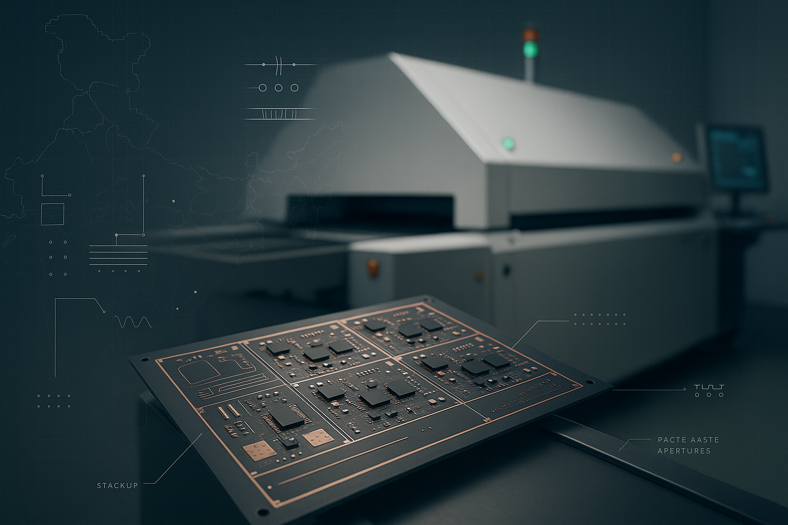
Modern electronics depend on high-frequency PCBs, especially in devices needing low signal loss and quick data transfer. Two most common forms of surface-mount packaging for integrated circuits are Ball Grids Array (BGA) and Land Grid Arrays (LGA). BGA makes the connections using solder balls; LGA connects with corresponding pads on the PCB using flat contacts on the underside of the package.
Designing effective, high-performance electronics depends on a knowledge of the variations between LGA and BGA. Usually used in CPUs and other high-power devices, LGA's dependability and simplicity of replacement make sense.
On the other hand, BGA is preferred for its great electrical performance and small form-fits for tablets, smartphones, and other small devices. The performance and dependability of high-frequency PCBs can be much affected by the decision between LGA and BGA, thereby stressing the need of choosing the suitable package for particular uses.
Key Highlights
- A Ball Grid Array (BGA) is a kind of surface-mount packaging used for integrated circuits characterised by an array of solder balls on the underside of the package.
- A Land Grid Array (LGA) is a kind of surface-mount packaging for integrated circuits designed with a grid of flat contact pads.
- LGA is mainly used for devices that require dependability and easy maintenance while BGA is required where space economy is important.
- The key soldering techniques for LGAs are surface preparation, flux alignment, and alignment.
- FCLGA (Flip Chip Land Grid Array) is a method of surface-mount packaging whereby the silicon die is flipped and bound directly to the substrate,
- LGA packaging process requires various steps like substrate preparation, die attachment, wire bonding, encapsulation, and pad metalization.
- You must consider various factors like cost, manufacturing implications, and performance before choosing between BGA and LGA.
Understanding Ball Grid Array (BGA)
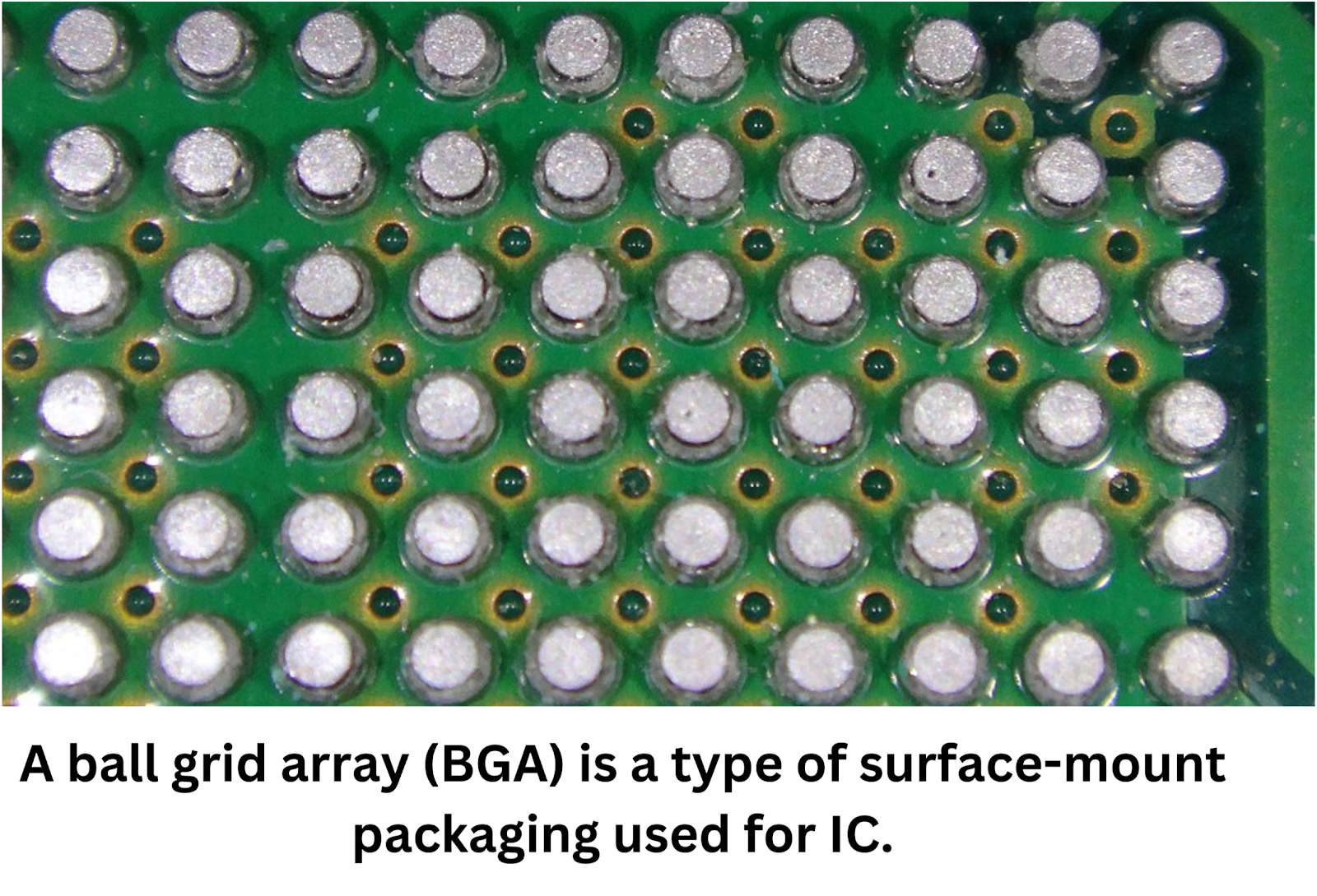
Characterised by an array of solder balls on the underside of the package, a Ball Grid Array (BGA) is a kind of surface-mount packaging used for integrated circuits. These solder balls give a more effective and small connection to the PCB than conventional pins.
Due to its reduced inductance and resistance, the BGA package's architecture permits enhanced thermal and electrical performance.
Moreover, they provide major design and manufacturing advantages; thereby BGA packages are extensively applied in electronics.
For high-density PCB designs, their small size and high pin density make them perfect since they let more components be placed on one board without losing performance.
Particularly in products like smartphones, laptops, and high-performance computer systems, BGA packages find common use in CPUs, memory modules, and complicated ASICs. Modern electronic design favours the BGA's capacity to offer strong connections and effective heat dissipation.
Understanding Land Grid Array (LGA)
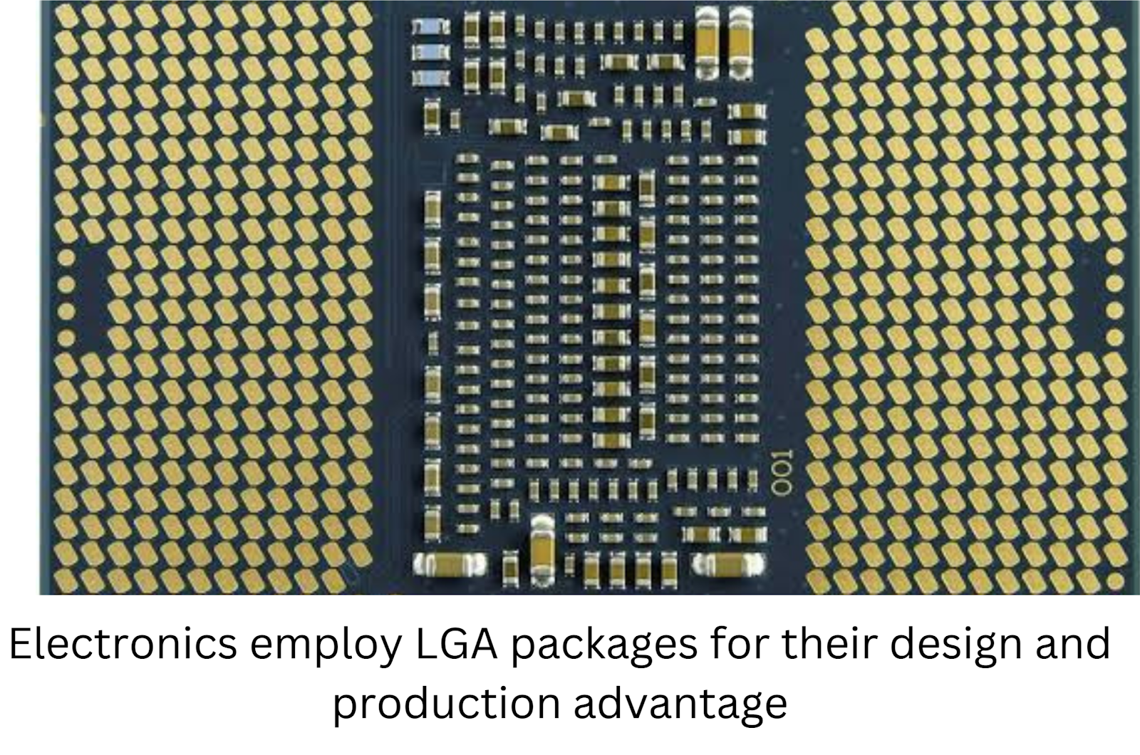
Designed with a grid of flat contact PCB pads on the underside of the package, a Land Grid Array (LGA) is a kind of surface-mount packaging for integrated circuits. LGA packages depend on direct contact between these pads and the PCB's matching pads unlike BGA, which employs solder balls.
Comparatively to soldered connections, this topology makes rework and inspection easier. Electronics employ LGA packages for their design and production advantages—high pin density and dependable mechanical connections among other things. Their structure fits high-frequency uses since it improves signal integrity and lowers inductance.
LGA packages find common use in CPU sockets and high-performance computing components, where flawless thermal performance and simple replacement are very vital. LGA packages are widely used in servers, desktop computers, and complex networking equipment where their strong connections and simplicity of handling help to ensure the general dependability and performance of the system.
Overview of CPU Sockets
On a computer's motherboard, a CPU socket is a physical interface used to house and link the CPU to the system. It guarantees a safe mounting of the CPU and helps to enable communication between it and other parts.
LGA (Land Grid Array) and BGA (Ball Grid Array) CPU sockets differ in their structure and connection techniques among other varieties. Simple replacement and upgrading are made possible by LGA sockets' flat contact pads connecting to the CPU's pads. By comparison, BGA sockets are more difficult to repair but contain soldered connections that provide a stable and consistent binding.
CPU installation and performance depend on socket compatibility; the improper socket could cause the CPU to malfunction. Guaranturing best performance, effective heat dissipation, and system stability by matching the motherboard and CPU socket guarantees Knowing these differences facilitates the choice of components for either creating or upgrading a computer system.
Installing a CPU on an LGA Socket Motherboard
Installing a CPU on an LGA socket motherboard involves several precise steps:
- Make sure your workplace is clean, free of static.
- Get the tools you need—a screwdriver and thermal paste.
- Release the CPU socket lever to open the lid for sockets.
- Coordinate the CPU with the socket. Verify the CPU's notches align with the alignment keys of the socket.
- Carefully slide the CPU into the socket such that all pins line up without using too much force.
- Pressing down the lever will lower the socket cover and secure it.
- Apply a tiny bit of thermal paste on top of the CPU. Set up the cooler.
- Attach the CPU cooler, making sure it is securely in position to guarantee efficient heat dissipating.
Important factors are holding the CPU by its edges to avoid harming pins and guaranteeing correct alignment to prevent bent pins. Using too much thermal paste—which could lead to overheating—and applying too much force—which might harm the CPU or socket—common mistakes to avoid are those ones.
Comparing LGA and BGA Packages
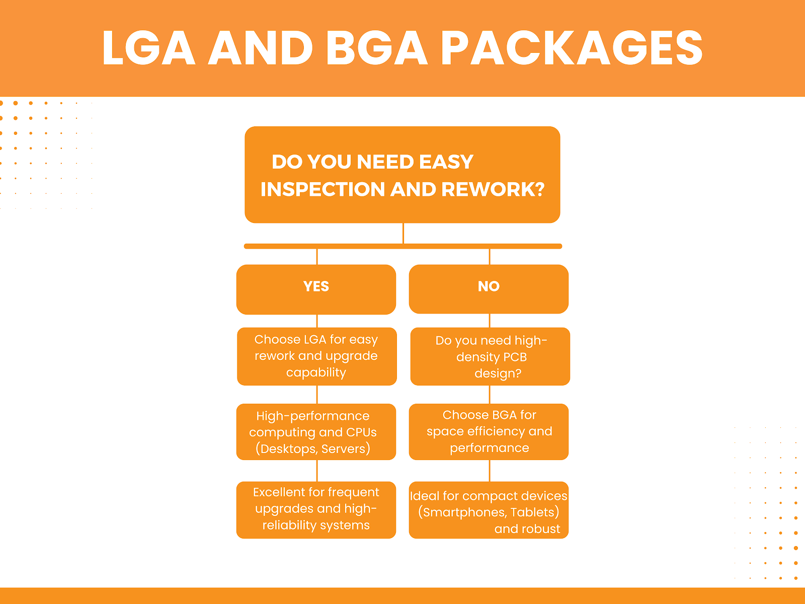
Their application scenarios and connection methods define LGA (Land Grid Array) and BGA (Ball Grid Array) packages.
From a grid of flat contact pads on the underside of the chip, LGA packages link to similar pads on the PCB. High-performance computers and CPUs where frequent updates may be needed to find LGA ideal since this architecture allows for straightforward investigation, rework, and replacement.
BGA packages form connections using solder balls, which provide strong and consistent bonds but are more difficult to examine and replace. BGAs offer remarkable electrical performance and heat dissipation, tailored for compact, high-density PCB designs in smartphones, tablets, and other space-constrained devices.
LGA is selected for desktop PCs and servers among other environments needing exceptional dependability and simplicity of maintenance. Applications where space economy and performance are very important demand for BGA.
Pros and Cons of LGA and BGA
LGA Packages:
Advantages:
- Ease of Inspection and Rework: LGA packages can be easily inspected and reworked. It happens due to their flat contact pads.
- Upgradability: CPUs and other components using LGA can be easily replaced. It makes them ideal for systems that require frequent upgrades.
- Reliability: The flat contacts provide robust and reliable mechanical connections.
Disadvantages:
- Contact Issues: Over time, the flat contacts can suffer from poor connection quality due to dust or wear.
- Complex Installation: The installation process requires careful alignment to avoid bent pins.
BGA Packages:
Advantages:
- Compact Size: BGA packages are smaller, making them ideal for high-density PCB designs.
- Enhanced Electrical Performance: Solder balls provide lower inductance and resistance. It improves electrical performance.
- Better Heat Dissipation: The design allows for efficient heat transfer, reducing overheating risks.
Disadvantages:
- Difficult to Inspect and Repair: Once soldered, BGA packages are challenging to inspect and repair.
- Permanent Installation: Components using BGA are not easily replaceable, making upgrades difficult.
Components Used in LGA vs. BGA
LGA Packages:
Common Components:
- CPUs: LGA packages are widely used for desktop and server CPUs. They can be found in Intel's Core and Xeon series.
- High-performance Microcontrollers: LGA are used in systems requiring frequent upgrades and high reliability.
- FPGA and ASICs: Suitable for applications needing robust connections and easy rework.
Compatibility and Integration Considerations:
- Socket Compatibility: Ensure the motherboard socket matches the LGA type. It is crucial for proper installation and performance.
- Thermal Management: Adequate cooling solutions are necessary due to the high power consumption of components like CPUs.
- Ease of Replacement: Components can be easily replaced or upgraded, making LGA ideal for high-maintenance systems.
BGA Packages:
Common Components:
- Memory Modules: Commonly used in RAM, NAND flash memory, and other high-density storage solutions.
- Microprocessors: Found in mobile devices, gaming consoles, and embedded systems due to their compact size.
- Chipsets and GPUs: Utilised in high-performance computing and graphics processing where space efficiency and thermal performance are critical.
Compatibility and Integration Considerations:
- Soldering Precision: Requires precise soldering techniques to ensure reliable connections.
- Thermal and Electrical Performance: BGAs offer superior thermal management and electrical performance. They are crucial for compact devices.
- Permanent Installation: BGAs are not easily replaceable, so compatibility must be carefully considered during the design phase.
Ease of Connection and Replacement for LGA vs. BGA
LGA packages, with their flat contact pads, provide simple PCB component replacement and connection. CPUs and high-performance components that might require regular upgrades would find this design perfect since it lets simple inspection and rework possible. Challenges include, nevertheless, the possibility of bending pins during installation and guaranteeing correct alignment to prevent connection problems. Using a CPU installation tool to precisely orient the chip and guaranteeing a clean, dust-free workspace to keep contact quality would help one to manage these difficulties.
BGA packages improve electrical performance and heat dissipation by offering strong, permanent bonding made possible by their solder ball connections. But in connection and replacement, they provide major difficulties since rework is difficult and the soldering process calls for accuracy. Using X-ray inspection tools and modern reflow soldering methods can guarantee dependable connections and help to control these issues. Though it remains more complex than with LGA packages, dedicated rework stations with hot air and infrared heating can help with desoldering and replacement for repairs.
Use of LGA and BGA in Microprocessors
In microprocessor design, LGA packages offer dependable connections and simplicity of replacement—qualities absolutely vital for high-performance computing. Desktop and server CPUs would be fit for them as they have great thermal management and high pin density. Intel's C2ore and Xeon lines, for instance, use LGA packaging to enable maintenance and updates. Superior signal integrity and low inductance made possible by LGA's design improve system performance generally in high-power applications.
Because of its clever use of space and strong electrical connections, BGA packages shine in microprocessors for mobile and small devices. Crucially for high-density, high-performance uses, they offer reduced electrical resistance and improved heat dissipation. Among them are Apple A-series chips and ARM-based CPUs found in tablets and cellphones. The small form factor that BGA's architecture offers helps devices where space and power economy are critical to integrate into.
LGA is quite effective in high-power, upgradable systems such as desktop computers and servers; BGA is best for mobile and embedded systems needing small, high-density architectures. Customised to their particular need, both packages significantly improve microprocessor performance.
Which is Better: BGA or LGA?
The particular application and needs will help one decide which of BGA or LGA is better. Due to their solder ball connections, which improve electrical performance and thermal management, BGA packages are suited for small, high-density designs in mobile devices and high-performance computing. LGA packages fit desktop and server CPUs when regular upgrades are required since their flat contact pads enable simple examination and replacement, hence offering ease of use and maintenance.
Cost factors show that although LGAs may have lower beginning costs but must be carefully handled to prevent pin breakage, BGAs may have higher production costs because of the precision needed in soldering. Another consideration is ease of use; LGA packages are easier for repairs and upgrades; BGA packages are more difficult to modify and replace.
In conclusion, LGA is favoured for systems needing frequent maintenance and updates, including desktop and server environments; BGA is suitable for high-performance, space-constrained applications including mobile devices and tablets. The decision will rely on juggling cost, performance requirements, and simplicity of maintenance.
Soldering Techniques for LGA Packages
The soldering process for LGA packages involves precise techniques to ensure reliable connections between the flat contact pads on the package and the PCB.
Key Techniques
- Surface Preparation: Clean the PCB pads thoroughly to remove any contaminants.
- Flux Application: Apply a suitable flux to the PCB pads to enhance solder flow and adhesion.
- Alignment: Carefully align the LGA package with the PCB pads using an alignment tool to prevent pin misalignment.
Tools Used
- Reflow Soldering Machine: Provides controlled heating to melt solder paste applied on the pads, ensuring uniform solder joints.
- Hot Air Rework Station: Used for reflowing solder joints and reworking if necessary.
- Alignment Tools: Essential for positioning the LGA package accurately.
Common Challenges
- Alignment Issues: Misalignment can lead to poor connections or shorts. Overcome this by using precise alignment tools and techniques.
- Solder Bridges: Excessive solder can create bridges between pads. Use the correct amount of solder paste and reflow profiles.
- Thermal Management: Ensure uniform heating to prevent thermal stress. Use a reflow oven with accurate temperature control.
Common LGA Soldering Problems and Solutions
Common LGA Soldering Problems:
- Misalignment of Contacts: Misaligned PCB pads can cause poor electrical connections.some text
- Solution: Use precise alignment tools and carefully place the LGA package on the PCB. Employ inspection tools like microscopes to verify alignment before soldering.
- Cold Solder Joints: Incomplete reflow results in weak joints.some text
- Solution: Ensure the reflow profile matches the solder paste specifications, providing adequate heat and time for proper solder flow.
- Solder Bridges: Excess solder can create shorts between adjacent pads.some text
- Solution: Apply the correct amount of solder paste and use a PCB stencil for uniform application. Inspect the joints post-reflow and use solder wick or desoldering tools to remove excess solder.
- Insufficient Wetting: Poor adhesion between the solder and pads.some text
- Solution: Clean the PCB and LGA pads thoroughly before soldering. Use high-quality flux to improve solder flow and adhesion.
Tips for Reliable Solder Joints:
- Maintain a clean work environment to prevent contamination.
- Use high-quality solder paste and flux.
- Follow the recommended reflow profile closely.
- Conduct thorough inspection post-soldering to ensure all joints are properly formed.
Inspection Techniques for LGA Packages
- Visual Inspection: Investigating solder junction alignment and integrity under a microscope. This simple approach finds clear flaws such inadequate solder, misalignment, or solder bridges.
- Automated Optical Inspection (AOI): Cameras on machines help them to automatically find flaws on the PCB. For misaligned components, solder bridges, and either insufficient or excess solder, AOI is quite successful.
- X-ray inspection: It is used to check under the LGA packaging concealed solder joints. Not seen to the unaided eye, interior flaws including voids, cracks, and missing solder joints can be found using X-ray machines.
Importance of Inspection: Maintaining LGA package dependability and quality depends on inspection. Early in the production process, it helps to find and fix flaws, therefore lowering the chance of field failures and guarantees that the devices satisfy strict performance and safety criteria.
Examples of Tools and Methods:
- Microscopes: For detailed visual inspection.
- AOI Systems: For automated, high-speed inspection.
- X-ray Machines: For non-destructive internal inspection.
Understanding FCLGA
Using solder bumps, FCLGA (Flip Chip Land Grid Array) is a method of surface-mount packaging whereby the silicon die is flipped and bound directly to the substrate, hence improving electrical and thermal performance. Compared to conventional LGA, this design permits a more compact package and shorter electrical paths, improving signal integrity and accelerating data transmission.
Differences from Standard LGA:
- Die Orientation: Unlike conventional LGA where the die is positioned on top of the substrate, with FCLGA the die is flipped and direct contact with the substrate is made possible.
- Thermal and Electrical Performance: Because the die and the substrate are directly connected, FCLGA offers better heat dissipation and lowered electrical resistance.
- Compact Design: Flip chip design produces a more compact package that qualifies for high-density uses.
Applications and Benefits:
Applications like CPUs in servers, desktops, and laptops in high-performance computers make FCLGA extensively used. It especially helps in settings needing fast data processing and effective heat dissipation. The direct die-to---substrate connection improves thermal management so the chips may run at faster speeds without overheating. Furthermore, the shorter electrical lines enhance signal integrity, which is vital for uses requiring fast and consistent data flow.
The LGA Packaging Process
- LGA Packaging Process:
- Substrate Preparation: Clean and prepare the substrate with precise pad patterns to ensure optimal contact with the LGA package.
- Die Attachment: Attach the silicon die to the substrate using adhesive or solder, ensuring alignment with the contact pads.
- Wire Bonding: Connect the die to the substrate with fine wires to establish electrical connections.
- Encapsulation: Encapsulate the die and wire bonds with protective materials to safeguard against environmental damage.
- Pad Metallization: Metallize the contact pads to enhance conductivity and ensure robust connections with the PCB.
Key Considerations:
- Precision Alignment: Ensuring accurate alignment of the die and substrate is critical to avoid misalignment and connection issues.
- Cleanliness: Maintaining a clean environment prevents contamination that could affect the solder joints' quality.
Quality Control Measures:
- Automated Optical Inspection (AOI): Used to detect alignment and soldering defects.
- X-ray Inspection: Ensures the integrity of internal connections and identifies hidden defects.
- Electrical Testing: Verifies the functionality of the LGA package by checking for continuity and signal integrity.
Applications of LGA and BGA Components
Applications of LGA Components:
- High-Performance Computing: Because they are easily replaced and upgraded, LGA packages—such as those found in Intel Core and Xeon series—are extensively employed in desktop CPUs.
- Servers and Data Centers: LGA is recommended for server CPUs since it provides strong connections and helps regular upgrades.
- Telecommunications: Applied in routers and networking devices, telecommunications offer dependable and high-speed data processing capability.
Applications of BGA Components:
- Consumer Electronics: Because of its small size and high-density integration, BGA packages—which abound in tablets and smartphones including Apple A-series CPUs—are rather common.
- Telecommunications: Applied in high-frequency transceivers and communication modules, telecommunication provides outstanding heat control and electrical performance.
- Automotive: Applied in advanced driver-assistance systems (ADAS) and infotainment systems, automotive technologies gain from their durability and capacity to survive demanding surroundings.
Benefits in These Applications:
- LGA Packages: High-performance and upgradeable systems would find them perfect as their main advantage is their simplicity of replacement and maintenance. Their consistent mechanical connections provide reliability and lifetime in demanding uses. .
- BGA Packages: Superior electrical performance and heat dissipation provided by BGA components—necessary for high-density and high-speed applications—allow for manufacturing smaller devices. Their small form lets one use space more effectively, which is absolutely important for portable and space-limited gadgets.
Factors to Consider When Choosing Between LGA and BGA
When choosing between LGA and BGA packages, consider these key factors:
- Performance:some text
- LGA: Offers ease of replacement and reliable connections, ideal for high-performance computing and systems requiring frequent upgrades.
- BGA: Provides superior electrical performance and thermal management, suitable for compact, high-density designs like smartphones and tablets.
- Cost:some text
- LGA: Typically lower initial costs but may involve higher maintenance costs due to potential pin damage.
- BGA: Higher manufacturing costs due to precision soldering but lower maintenance costs due to robust connections.
- Manufacturing Implications:some text
- LGA: Easier inspection and rework, making it preferable for applications where maintenance and upgrades are common.
- BGA: Requires precise soldering and inspection tools like X-ray machines, making it more suitable for mass production of compact devices.
Practical Advice:
- For high-performance, upgradeable systems (e.g., desktops, servers), LGA is the better choice due to its ease of rework and reliable connections.
- For space-constrained, high-density applications (e.g., mobile devices), BGA is preferable for its compact size and superior performance.
Conclusion: Choosing Between LGA and BGA
LGA and BGA packages have quite different performance, application, and construction. Because of their simplicity of inspection and rework, LGA packages—which have flat contact pads—are perfect for high-performance computing and systems needing regular upgrades. BGA packages, with solder ball connections, provide excellent electrical performance and thermal management, which qualifies for small, high-density uses like mobile electronics. Making wise judgments depends on an awareness of these differences; so, the selected package must match the particular needs of the application, balance performance requirements, cost concerns, and manufacturing consequences.
Table of Contents
Understanding Ball Grid Array (BGA)
Understanding Land Grid Array (LGA)
Overview of CPU Sockets
Installing a CPU on an LGA Socket Motherboard
Comparing LGA and BGA Packages
Pros and Cons of LGA and BGA
Components Used in LGA vs. BGA
Ease of Connection and Replacement for LGA vs. BGA
Use of LGA and BGA in Microprocessors
Which is Better: BGA or LGA?
Soldering Techniques for LGA Packages
Inspection Techniques for LGA Packages
Understanding FCLGA
The LGA Packaging Process
Applications of LGA and BGA Components
Factors to Consider When Choosing Between LGA and BGA
FAQ's
What is the easiest IC package to manually inspect?
The LGA (Land Grid Array) package is the easiest IC package to hand-check. Unlike BGA packages, which need more sophisticated inspection procedures, its flat contact pads provide simple visual inspection and rework, therefore facilitating the detection of alignment problems and solder faults.
Which IC packaging has the highest pin count capacity?
The best pin count capacity comes from BGA (Ball Grid Array) products. Their solder ball connectors let pins be densely arranged, hence increasing connections in a small space. For high-performance and high-density applications needing many interconnections, BGAs are therefore perfect.
Which package offers the most design flexibility?
LGA packages' simplicity of inspection, rework, and replacement gives them the most design freedom. This makes them appropriate for high-performance computer applications where regular updates and maintenance are required, therefore offering flexibility in design and long-term usability.
Which package is best for thermal management?
Thermal control calls for BGA packages. BGAs are perfect for uses with high thermal demand since the solder ball connections enable effective heat dissipating. In devices with considerable heat generation, such as high-performance CPUs, this guarantees dependable performance and lifetime.
Which one is best in High-Power Applications: BGA or LGA?
BGA packages shine in high-power uses because of their exceptional thermal management and electrical performance. Their greater handling of high current densities than LGA packaging qualifies them for small, high-performance electronics. LGA packages, however, match varying application requirements and are simpler to replace and manage.